

|

|

|

|


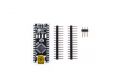
The OSEPP™ Nano is a breadboard-friendly, downsized version of the Uno board with much of the same functionality. The main workhorse is still the ATmega328P; however, the number of analog pins has gone up from four to eight. The other difference is the lack of a DC power connector.
| Microcontroller | ATmega328P |
| Clock Speed | 16 MHz |
| Flash Memory | 32 KB |
| SRAM | 2 KB |
| EEPROM | 1 KB |
| Operating Voltage | 5V |
| Input Voltage | 6-12 V |
| Digital I/O Pin Count | 14 (including 6 for PWM output) |
| Analog Input Pin Count | 8 |
| Other Connections | Mini-USB Serial communication (requires header) ICSP (requires header) |
| Dimensions | 1.73 x 0.71 x 0.31 inches (44.0 x 18.0 x 8.0 mm) |
| Power Source | Mini-USB |
Highlights:
- 8-bit AVR RISC-based microcontroller running at 16 MHz
- Single mini-USB connector for both power and serial communication
- Form factor is breadboard friendly
- Less than 1/3 the size of the OSEPP™ Uno
- Two extra analog input pins compared to the OSEPP™ Uno
- Compatible with existing Arduino software libraries
Features:
The ATmega328P comes with the Arduino bootloader preloaded. There are ICSP (In-Circuit Serial Programming) pinouts for the ATmega328 that can be used in conjunction with a header (sold separately) to optionally replace the bootloader.
The input or output pins can easily be brought out by soldering 0.100” headers to the pads. The board was designed to easily fit breadboards with the headers soldered on.
Availability:
| Stock Code | Product Name |
| NAN-01 | OSEPP™ Nano |
Notes:
This board is based off of the Arduino Nano designed by Gravitech, and is released under the
Creative Commons Attribution Share-Alike License. The original design can be found at
http://arduino.cc/en/Main/ArduinoBoardNano
Downloads:
| OSEPP Nano Schematic (PDF) | |
| OSEPP Nano EAGLE Files |  |
Learning Center:
Uploading Your First Sketch
- Get the Arduino software if you have not already
- Download from http://arduino.cc/en/Main/Software
- Unzip the zip file to somewhere like C:\ (on Windows), so you will end up with a folder like C:\arduino-0022
- Prepare for serial communication
- Connect the USB-B end of the cable into the board
- Connect the other end of the cable into a USB port on your PC/Mac
- If your computer prompts for drivers, point it to the “drivers\FTDI USB Drivers” subfolder of the Arduino software, e.g. “C:\arduino-0022\drivers\FTDI USB Drivers”
- You should now see the LED labeled ON near the reset button light up
- Load the sketch
- Open the Arduino software
- Open the LED blink sketch: File menu > Examples > Basics > Blink
- Select the Arduino Nano: Tools > Board > Arduino Nano
- Select the serial port: Tools > Serial Port. This is the serial port for the board’s built-in FTDI. If you do not know which one this is, you can find out by going into Device Manager > Ports (COM & LPT), and look for a “USB Serial Port (COMx)”
- Upload the sketch: File > Upload to I/O Board
- Wait for the “Done uploading” message in the bottom blue status bar
- The LED labeled L near pin 13 should now blink slowly
- Congratulations! You have successfully uploaded your first sketch to your board.